ARC’s goal is to be able to move around by attaching electromagnet from and to different points on a metal ceiling, so a launcher mechanism is required in order to launch the electromagnet from the robot body towards the ceiling. Several launching methods were explored including CO2, telescoping arm, flywheel, etc. We ultimately decided on the spring launching method given its many pros including simplicity of calculation, high life cycle, and repeatability.
One key issue was how to launch the electromagnet once the spring is fully compressed. We research different possibilities such as a pneumatic actuator to detach the driving gear away from the rack which compresses the spring, releasing the electromagnet. However, a mechanical system is the best to detach the teeth engagement because we did not want to introduce pneumatics onto the robot which would add weight and the onboard compressor could melt the 3D printed components. After discussions, we decided on using teeth uncompleted gears which will automatically release the rack once the gear rotates to a position where there are no gear teeth to engage the rack.
One key issue was how to launch the electromagnet once the spring is fully compressed. We research different possibilities such as a pneumatic actuator to detach the driving gear away from the rack which compresses the spring, releasing the electromagnet. However, a mechanical system is the best to detach the teeth engagement because we did not want to introduce pneumatics onto the robot which would add weight and the onboard compressor could melt the 3D printed components. After discussions, we decided on using teeth uncompleted gears which will automatically release the rack once the gear rotates to a position where there are no gear teeth to engage the rack.
Launcher Gearbox
|
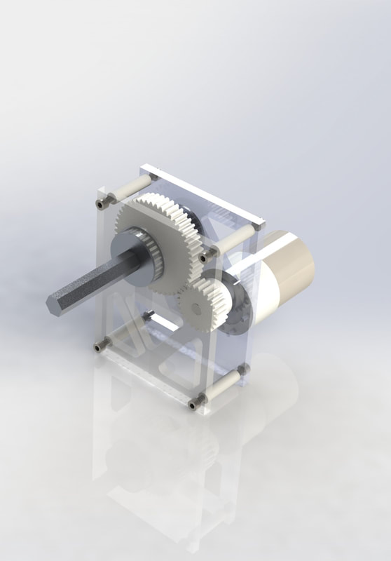
The launcher uses a gearbox to increase torque output from the motor. The two gearbox plates are 3D-printed, and connected using 3D-printed standoffs. We used a hex shaft and two hex bearings, as well as a hex collar and 3D-printed spacers to keep the large gear in place. The motor pinion is fixed to the motor shaft using a set screw.
To calculate the required gear ratio, we first determined several parameters, including the launcher’s spring constant and the output pinion diameter. The spring constant was determined by considering the kinematics of the launched electromagnet based on set launching and impact angles. This allowed us to calculate the required initial velocity of the electromagnet. We then calculated the required spring constant using conservation of energy. Kinematics drawing and calculation sheet shown below. |
|
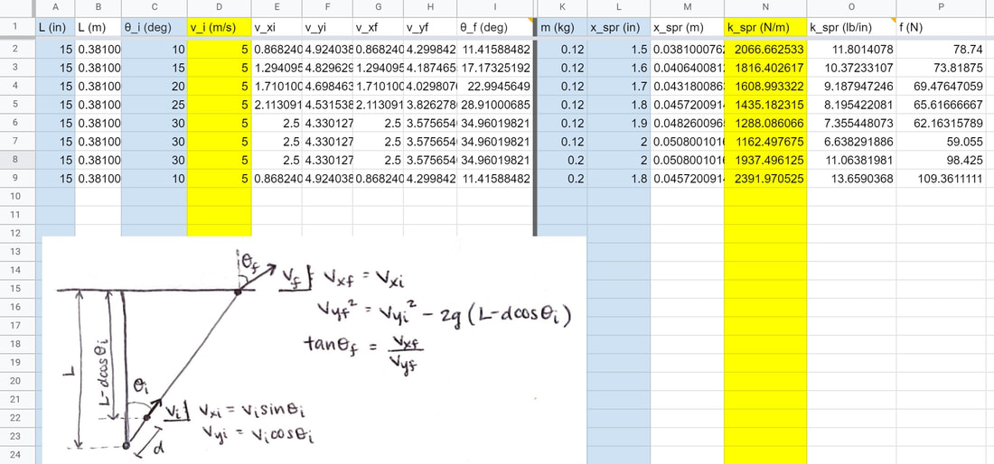
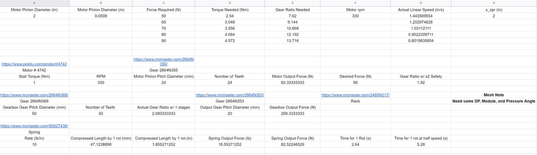
Based on our calculations and design parameters, we chose a spring with a spring constant of 10 lb/in (or 1751 N/m).
The output pinion diameter was determined by the desired spring compression distance of roughly 2 inches, or 50.8mm. Taking into account that the pinion is a ¾ partial tooth gear, we solved the equation ¾(pi)D = 50.8 mm to obtain a minimum pinion diameter of 21.6 mm. Based on this, we chose a pinion with a 24mm pitch diameter.
Using the obtained spring constant and pinion diameter, we calculated a required output torque as follows: T=k *x *R_pinion = (1751 N/m)(0.0508 m)(0.012 m)=1.067 Nm
Our Pololu motor’s maximum operating torque is 1 Nm, so with a FOS of 2, we obtained a desired gear ratio of 1.8. Based on these results, we chose to use 50-tooth and 24-tooth gears for a gear ratio of 2.1:1.
For the launcher gearbox, the components most likely to fail are the gearbox plates, as they are 3D-printed, and the spring compression requires a relatively large force. Additionally, to reduce weight, the plates have holes cut out, and are planned to be printed with 60% infill. To ensure that the plates would not fail, we conduct hand calculation then verify with Solidworks FEA. We first calculated the bearing force using the following equations and constant parameters values:
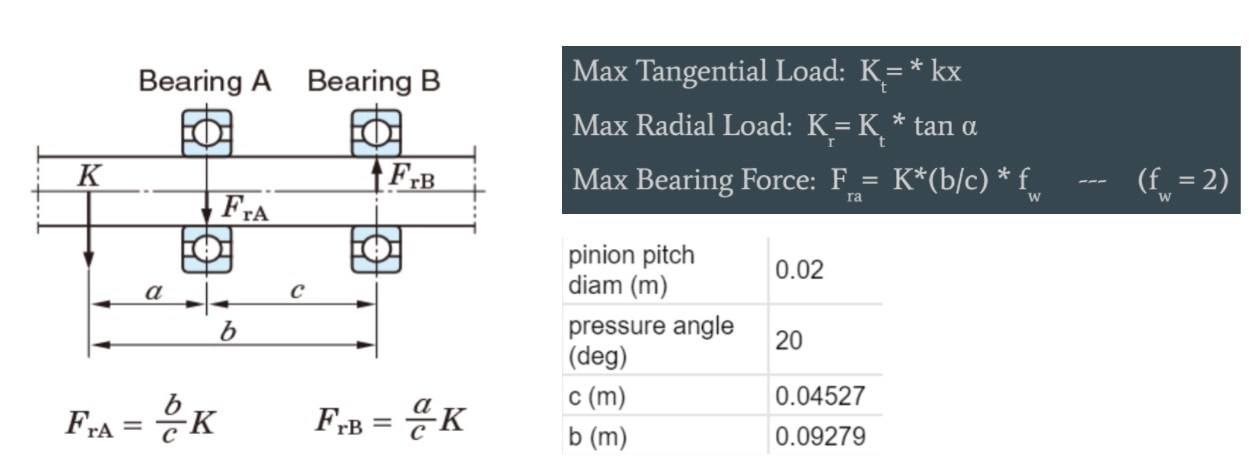
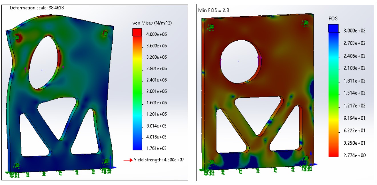
These calculations resulted in a maximum bearing force of 388 N, which we applied to the upper half of the bearing hole surface.
As shown in the FOS plot, the minimum FOS is 2.8. Although FEA is not accurate for 3D-printed parts (as it doesn’t account for the reduced infill and the printed layers) we believe that this FOS is sufficiently high to account for those factors.
As shown in the FOS plot, the minimum FOS is 2.8. Although FEA is not accurate for 3D-printed parts (as it doesn’t account for the reduced infill and the printed layers) we believe that this FOS is sufficiently high to account for those factors.
Launcher Barrel
|
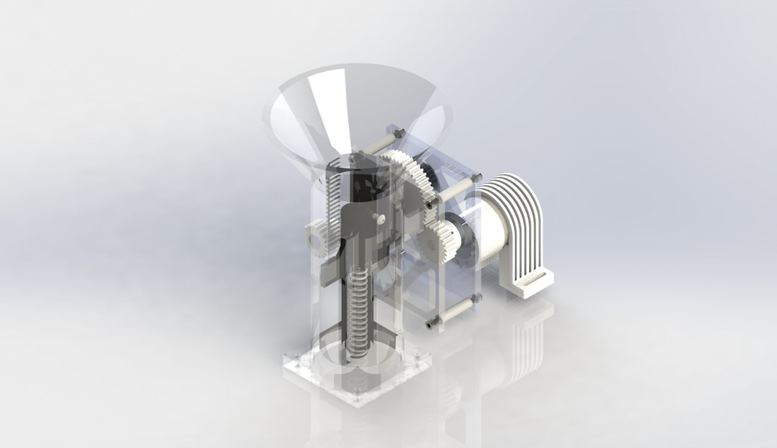
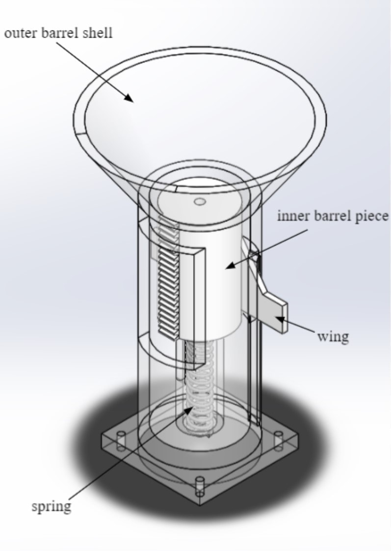
The barrel functions as the launching guide and utilizes a spring system to launch the electromagnet. It consists of two main components: an inner barrel piece and an outer barrel shell, connected with the spring. The spring was chosen based on its spring constant, which was calculated in the previous section. The inner piece functions as a launch pad that interacts with the spring to launch the electromagnet. The outer shell served as the main structural component of the barrel, including a funnel shape at the top that allows the electromagnet to be guided into the barrel. A hole runs through the system for the cable of the electromagnet to go through and into the reeling system. A concentric cylinder around the spring prevents undesired bending and ensure the spring can compress its maximum distance delivering the greatest possible force. A wing prevents the inner barrel from rotating during compression and launch, and transfer the load to the top of the slot otherwise experienced at the spring connection locations.
|
|
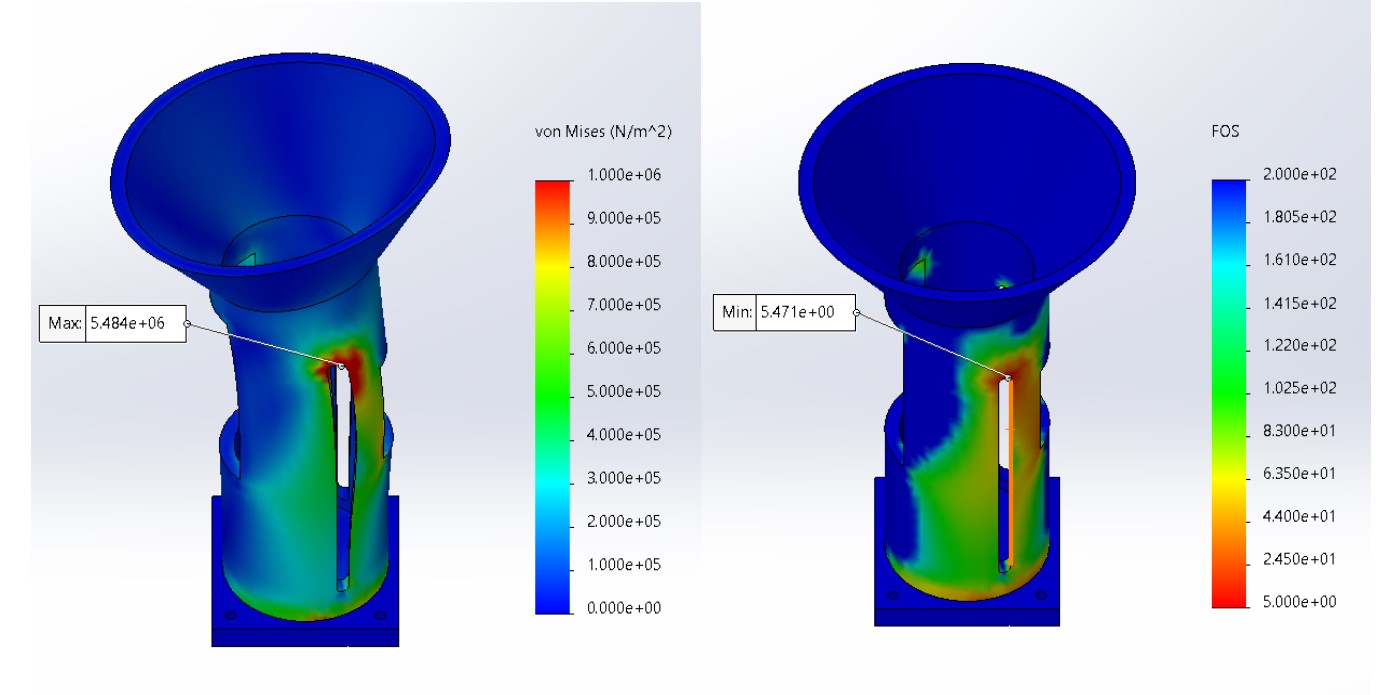
To ensure the barrel pieces would not fail during launch and reeling, FEA was done on the inner and outer barrel parts in Solidworks. In order to save on weight, the inner and outer pieces were to be 3D printed with 80% and 60% infill, respectively. The inner piece was put under the reeling force to mimic the impact of the electromagnet on its top surface.
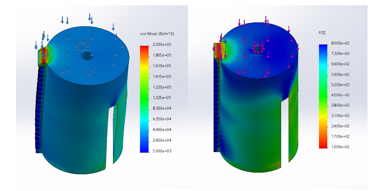
The FEA resulted in a FOS of 110, which we believe is still high despite it being 3D printed and at 80% infill. For the outer barrel shell, the same reeling force was used to show impact of the electromagnet on the top funnel part. FEA was first completed for impact on the entire rim and the inner wall of the funnel, both resulting in efficiently high FOS numbers. To better simulate the electromagnet’s direction on the barrel, FEA was done on a section of the rim of the funnel, which would be the weakest and most concentrated impact the electromagnet would possibly have on the barrel.
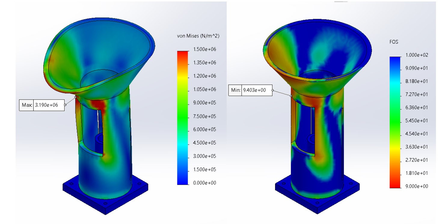
This FEA resulted in an FOS of 9.4, which is sufficient for the 60% infill planned for manufacturing. The top rim of the slot on the outer barrel shell was concerning since it had to withstand the entire force from the spring, transferred from the wing, during launching. This was simulated with the spring force calculated earlier when finding the spring to use. The resulting FEA had an FOS of 5.5, also sufficient for our printed barrel shell.