For ARC, a quick and sturdy reeling mechanism is necessary because it needs to both reel the electromagnet back into the launching mechanism once it detaches from the ceiling, and also maintain the robot’s altitude in air by clamping down on the wires that are attached to the electromagnet when the magnet is attached to the ceiling. This mechanism encounters a similar issue with the launcher, as we deemed it necessary to allow the wires to freely leave with the magnet when launching, meaning that there also needs to be a detaching mechanism to both allow the reeler to reel in the electromagnet when needed and the electromagnet to freely launch without any resistance. We decided on the same teeth uncompleted design based on similar reasoning mentioned in the launch mechanism.
Reeler Gearbox
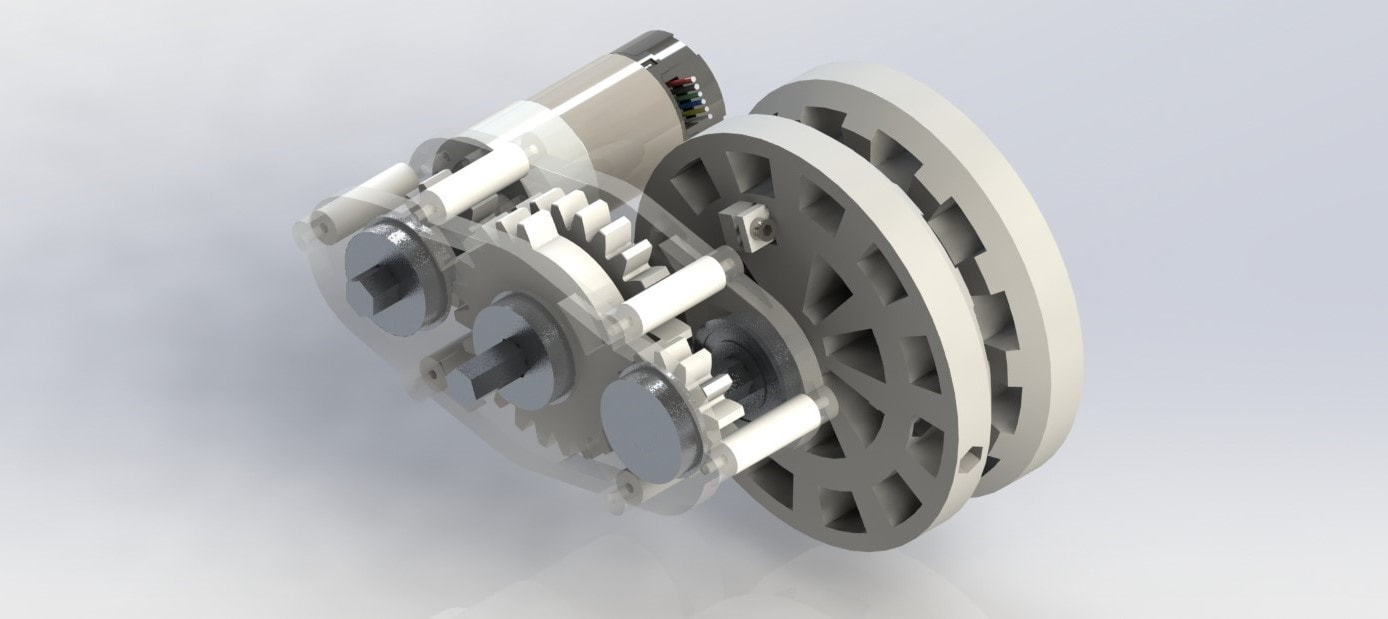
The reeler gearbox serves 2 purposes: to enable Motor Disengagement and to perform Torque Transformation.
Motor disengagement is required because after reeling the cable back into the robot, the cable will be launched back out for the next grappling action. This sequence of actions will occur repeatedly to create the swinging action that we desire. However, If the reeling motor is directly coupled to the reeling drum without disengagement, we risk damaging the motor by back-driving it. We needed a way to decouple or disengage the motor from the reeling drum when the launching action occurs. We came up with a “partial gear” design that allows simple disengagement without needing an additional actuator.
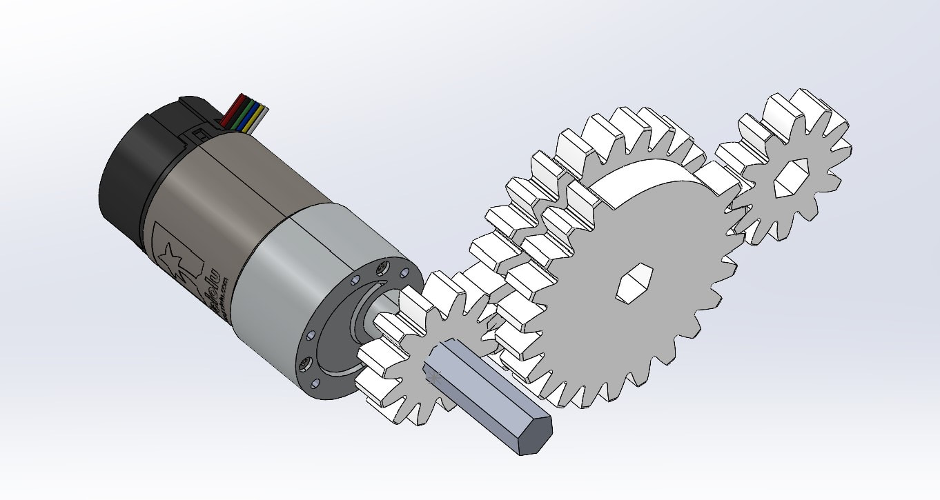
During the launching action, the partial gear will turn so that the bare spot faces the drum gear; this allows the drum to turn whilst decoupled from the rest of the gearbox/motor.
Motor disengagement is required because after reeling the cable back into the robot, the cable will be launched back out for the next grappling action. This sequence of actions will occur repeatedly to create the swinging action that we desire. However, If the reeling motor is directly coupled to the reeling drum without disengagement, we risk damaging the motor by back-driving it. We needed a way to decouple or disengage the motor from the reeling drum when the launching action occurs. We came up with a “partial gear” design that allows simple disengagement without needing an additional actuator.
During the launching action, the partial gear will turn so that the bare spot faces the drum gear; this allows the drum to turn whilst decoupled from the rest of the gearbox/motor.
The gearbox also needs to perform torque transformation because the weight of the robot places a tension on the cable, torqueing the drum gear and thus the partial gear, which eventually ends up torqueing the motor shaft. From calculations, if the motor were directly coupled to the partial gear, the torque on the partial gear would exceed the stall torque of the motor we chose, potentially causing damage. To solve this, the gearbox features an additional gear stage that reduces the amount of torque that the weight of the robot will enact on the motor shaft.
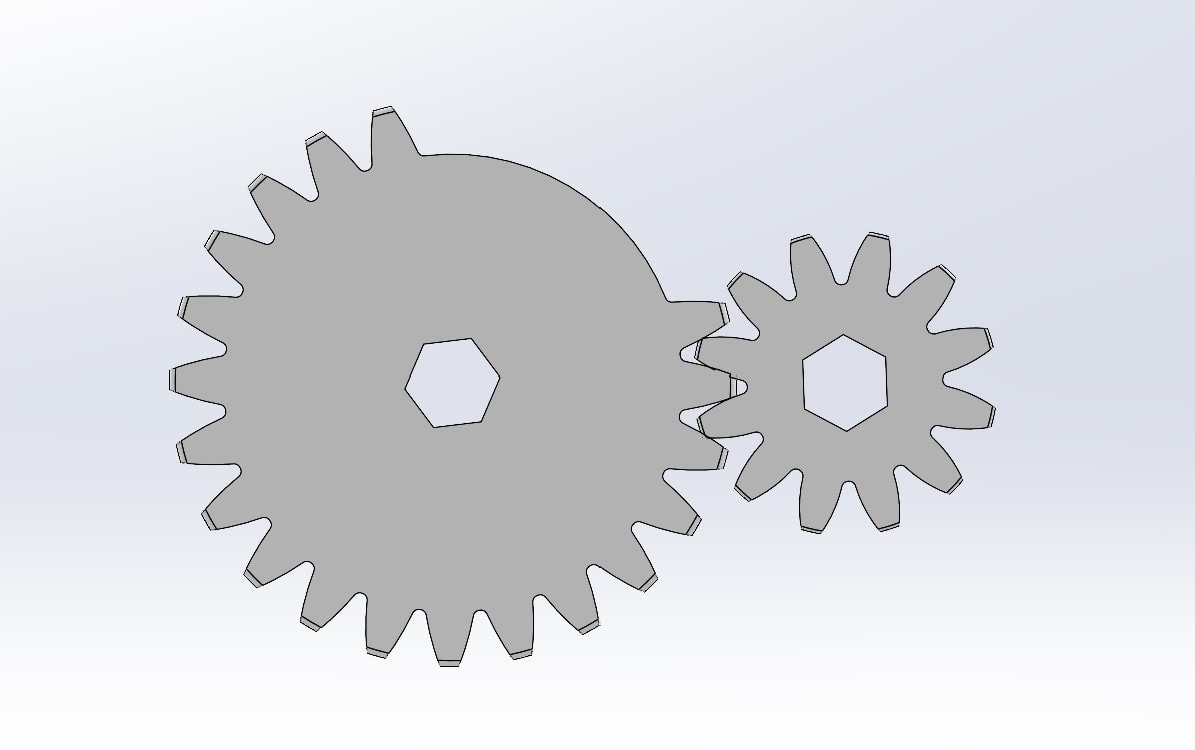
Partial gear stage calculations: The entire cable must be wound up by one rotation of partial gear
Tooth Ratio (Partial gear : drum) = (# of drum revolutions)/(1 rotation of partial gear) = (cable length)/(drum circumference) = 18 in/(7.5 in*pi) ≈ 1.52
If use 12 tooth gear on drum, need at least 12*1.52 ≈ 19 teeth on partial gear
Take a 24-tooth gear, cut out 5 teeth for 19-tooth partial gear
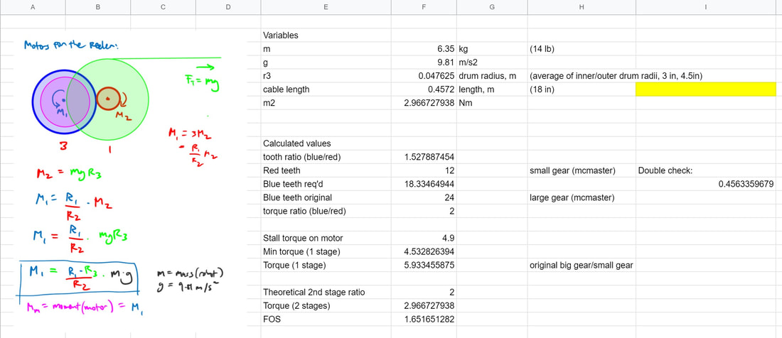
Reduction stage calculations: The motor stall torque must be considerably higher than torque on shaft
Theoretical mass of the robot = 14 lb ≈ 6.35 kg
Torque applied by tensional force of wire on drum gear = (robot mass)*g*(radius of drum)= (6.35 kg)*(9.81 m/s2)*(.047m) = 2.966 Nm
Torque applied to partial gear = (drum gear torque) * (partial:drum ratio) = 2.966 Nm*2 = 5.933 Nm
Stall torque of motor = 4.9 Nm
Use reduction stage with ratio = 1:2
12 tooth : 24 tooth gears
Torque after reduction stage = (partial gear torque) * (reduction ratio) = 5.933 Nm * 0.5 = 2.966 Nm
FOS = 4.9/2.966 = 1.65
Tooth Ratio (Partial gear : drum) = (# of drum revolutions)/(1 rotation of partial gear) = (cable length)/(drum circumference) = 18 in/(7.5 in*pi) ≈ 1.52
If use 12 tooth gear on drum, need at least 12*1.52 ≈ 19 teeth on partial gear
Take a 24-tooth gear, cut out 5 teeth for 19-tooth partial gear
Reduction stage calculations: The motor stall torque must be considerably higher than torque on shaft
Theoretical mass of the robot = 14 lb ≈ 6.35 kg
Torque applied by tensional force of wire on drum gear = (robot mass)*g*(radius of drum)= (6.35 kg)*(9.81 m/s2)*(.047m) = 2.966 Nm
Torque applied to partial gear = (drum gear torque) * (partial:drum ratio) = 2.966 Nm*2 = 5.933 Nm
Stall torque of motor = 4.9 Nm
Use reduction stage with ratio = 1:2
12 tooth : 24 tooth gears
Torque after reduction stage = (partial gear torque) * (reduction ratio) = 5.933 Nm * 0.5 = 2.966 Nm
FOS = 4.9/2.966 = 1.65
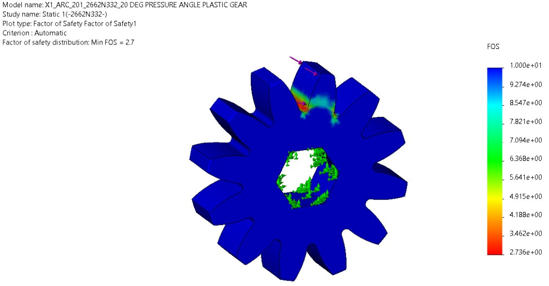
To ensure that our 3D printed gearbox would not plastically deform under the weight of the robot, we ran some FEA on a few critical components of the gearbox.
Most importantly, we wanted to ensure that the 3D printed gears would be able to handle the maximum load of the robot’s weight. The two drum gears, which experience the highest load, have approximately 3 times the gravitational force of the robot acting on the two meshing gear teeth at any time. Rounding 3 x 14 lbf then dividing by 2 to get a load of about 25 lbf per tooth (rounded up).
Most importantly, we wanted to ensure that the 3D printed gears would be able to handle the maximum load of the robot’s weight. The two drum gears, which experience the highest load, have approximately 3 times the gravitational force of the robot acting on the two meshing gear teeth at any time. Rounding 3 x 14 lbf then dividing by 2 to get a load of about 25 lbf per tooth (rounded up).
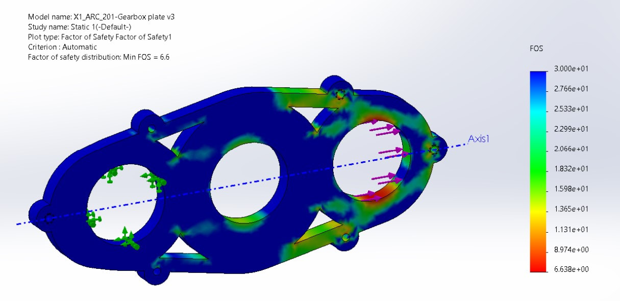
The other component that we wanted to analyze was the gearbox housing, specifically the plates. Using similar equations found in the Launcher Gearbox calculations, we were able to find a bearing load of approximately 250N. Then apply this load to our gearbox side plates in FEA.
Reeler Drum
|
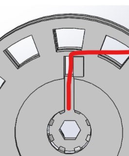
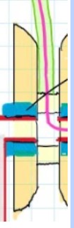
The drum by itself is quite a simple unit, as its only job is to store the cable and act as the point of contact between the cable and the rest of the robot. The cable is first guided into the drum’s surface with chamfered edges, then wrapped around the drum until it makes a 90 degree turn into a cavity cut out of the drum, which leads directly to the central bore.
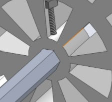
From there, wires contained in the cable housing leave the drum on the circular bored side (which will be the mount point of a bearing) to continue to a central post in the chassis (in red). On the opposing side of the circular bore, the output hex shaft from the reeler gearbox will be inserted and secured by a bolt through the drum. |
|
|
